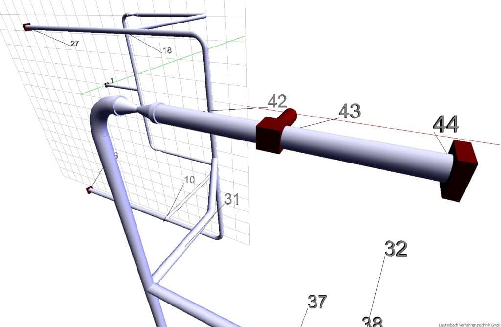
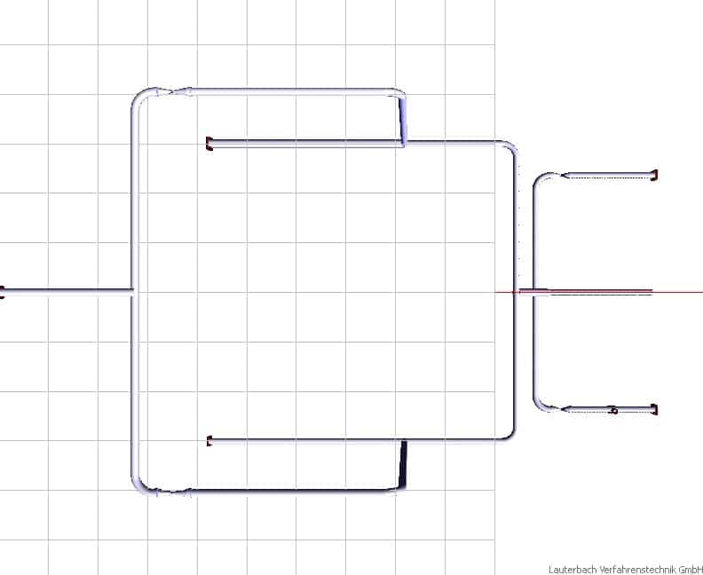
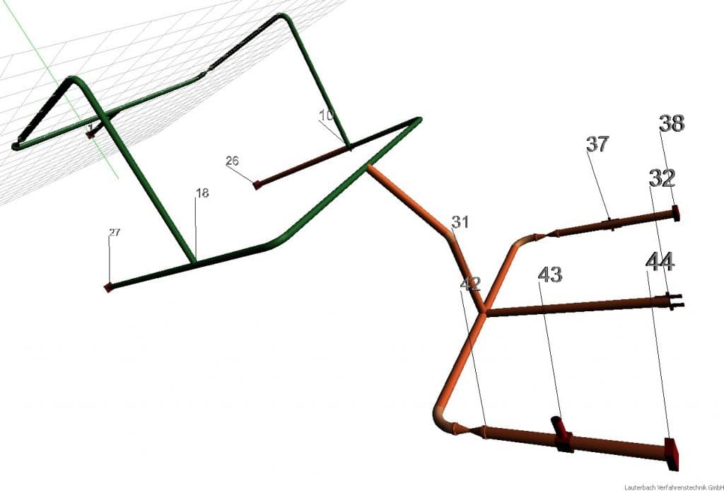
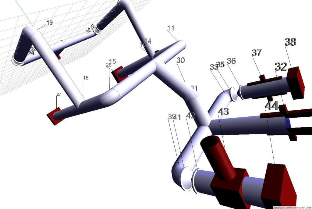
Calculation of 3-D piping systems with the program LV PIPE II
Requires at least MS Office 2013 32-bit.
(64-bit Add-In on request)
Runs under Windows 10 32/64-bit.
Digitally signed by GlobalSign (CA)
The PIPE user interface is completely created in Excel. The Excel environment has the advantage that you as a user can enter your own data, links and freely create the documentation of your projects. The results of a calculation can be treated separately from the input (Excel workbook).
Features
LV PIPE II determines
Support forces and moments
Pipe forces and moments
displacements
Stresses according to:
- ANSI B31.1
- ANSI B31.3
- FDBR
- EN 13480
- DVS (plastic pipes)
Spring hanger data/ catalogue
nozzle load
Wind loads, seismic loads
friction
Bearing with clearance
Singular supports
Different load cases and freely definable load case combinations
If you click on this video we will play the video, load scripts on your device, store cookies and collect personal data. This enables [Google Ireland Limited, Irland] to track activities on the Internet and to display advertising in a target group-oriented manner. There is a data transfer to the USA, which does not have EU-compliant data protection. You will find further information here.
Jmx0O2lmcmFtZSB0aXRsZT0mcXVvdDtWZXJzY2hpZWJ1bmcgZWluZXMgUm9ocmxlaXR1bmdzc3lzdGVtcyBpbiBMViBQSVBFJnF1b3Q7IHdpZHRoPSZxdW90OzY5NiZxdW90OyBoZWlnaHQ9JnF1b3Q7NTIyJnF1b3Q7IHNyYz0mcXVvdDtodHRwczovL3d3dy55b3V0dWJlLmNvbS9lbWJlZC9abVpFRmR1bEs3MD9mZWF0dXJlPW9lbWJlZCZxdW90OyBmcmFtZWJvcmRlcj0mcXVvdDswJnF1b3Q7IGFsbG93PSZxdW90O2FjY2VsZXJvbWV0ZXI7IGF1dG9wbGF5OyBjbGlwYm9hcmQtd3JpdGU7IGVuY3J5cHRlZC1tZWRpYTsgZ3lyb3Njb3BlOyBwaWN0dXJlLWluLXBpY3R1cmUmcXVvdDsgYWxsb3dmdWxsc2NyZWVuJmd0OyZsdDsvaWZyYW1lJmd0Ow==
Displacement of a piping system
The data are determined for the mere weight load case (assembly), the mere temperature load case (starting / stopping) and for the combination load case (operation). For an easier evaluation, the most important variables can be displayed graphically. The LV PIPE II AddIn is particularly suitable for the calculation of nozzle loads in pressure vessel construction. With the modules FEM (Finite Element Method) and WRC all verifications according to the Pressure Equipment Directive can be performed.
Program Comparison LV PIPE II / CAESAR 2 / RAMPA and START by Jelena Priss, Ivan Klevtsov Tallinn University of Technology (PDF)
The maximum number of full load cycles is documented.
The displacementof the piping system can be animated for each load case.
The the sake of clarity, the node labeling is displayed anti-perspectively (of equal size). It is rotatable and scalable.
A header and footer are available for keywords and material documentation.
Pipelines clicked on in the input sheet are simultaneously highlighted in the graphic.
Buckling rings can be taken into account.
Often used assemblies / pipeline elements can be predefined and used as often as desired.
CAD options
- Export of graphics as 2-D or 3-D DXF format for further processing
- Up to 12 stress ranges freely adjustable
- Predefined views can be set as required
 Freely rotatable representation of the pipe system
 Representation of the deformed/undeformed system.
 Predefined views (top, left, right, perspective)
 Colour representation of the stresses
 Pipe size can be freely displayed, Show all nodes
 Node labeling size and spacing adjustable
 Show independent sections
 Background color freely selectable
Combination with other LV programs (if purchased)
FE verification of connected nozzle
The pipeline forces and moments are directly transmitted to the FE program FEM developed by LV.
Stability verification according to DIN 18800 Part 4 and DIN EN 1998-1 (Eurocode 8)
Transfer of all relevant data to the corresponding LV module. The results can be output to MS Word.
Calculation of flanges with superimposed pipe forces
The pipeline forces and moments) are transferred directly to an LV flange module (e.g. EN 1591, DIN V 2505, ASME VIII, AD 2000).
Calculation of metallic industrial piping according to DIN EN 13480
Piping components under internal pressure according to EN 13480-3 chapter 6 (Module ER06)
Dished heads under internal pressure according to EN 13480-3 chapter 7.1 (Module ER07)
Openings and branches according to DIN EN 13480-3 chapter 8 (Module ER08)
Combination package ‘EUROPIPE’
Program LV Pipe II + Basic package EN13480
|
on request
|
see also: