Overview of module package AD 2000 / Section S
The AD 2000 bulletins series S apply for the design of pressure vessels under static and fatigue loading. The bulletin AD S1 offers a simplified method for the design of pressurized components under varying pressure. A more detailed fatigue design for varying pressure, temperature differences or additional external forces and moments can be accomplished using AD-S2. The bulletins S3/0 to S3/5 apply for vessel support design. AD S3/6 serves the calculation of local stress in the vessel wall in the region of nozzles by additional external loads.
Additional information and hints for pursuing calculations or deficiencies in the code can be displayed dynamically by using the InfoBrowser.
The calculation documentation is similar to the EN standards.
Interfaces to CAD systems on request.

Project – BOM
The Project module summarizes operational and test data, as well as the main parts of a pressure vessel including main geometrical data and used material in one working sheet. For the final calculation, the specified modules are adjusted and their data are connected to the working sheet.
The Project module determines which calculation code is used and according to which standard the material definition should be done.
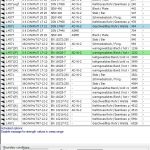
Material Database – WERK
Selection and documentation of materials for the design of pressure vessels
The program determines the permissible strength characteristics depending on temperature, component geometry, the code and delivery standard. All values are displayed, can be printed, copied to the clipboard, stored in a file (e.g. for further processing with MS WORD) or transferred to any calculation modules such as AD 2000/EURONORM/ASME/TRD
The material server is bilingual. You can switch from German to English and vice versa.
 Fully integrated material database
The additional information needed to calculate the max.
allowable working pressure, test pressure and reference pressure for AD S1
is provided. It is also possible to set the boundary conditions
yourself, e.g. for pressure shock and explosion wave
calculations.
The weld factors for the load alternation calculation are suggested by
the program and can be adapted to the conditions
at any time.
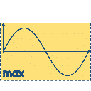
S1 – Simplified calculation for cyclic loading
In the case of fluctuating loads, material fatigue must be taken into account
for steels with high yield strength. The number of pressure fluctuations
to be expected during operation must therefore not exceed the permissible
number of load cycles.
The S1 module determines the allowable number of stress cycles under consideration of the pressure, temperature and design factors.
The number of allowable load cycles is determined by the Nzul module.
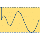
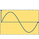
S2 – Calculation for cyclic loading
If the load changes over time (vibration stress)
due to internal pressure, temperature differences or additional forces
and moments, failure due to cracking must
be excluded.
The S2 module provides the following options:
- Calculation of the decisive equivalent stress range in the
overelastically stressed area in accordance with AD 2000 – Rules and Regulations S2 /
section 6
- Calculation of the permissible stress ranges for a known
number of load cycles on welded and non-welded components in accordance with AD 2000 –
regulations S2 / sections 7.1 and 7.2
- Calculation of the permissible number of load cycles with known
stress range at welded and non-welded component
areas according to AD 2000 – Standards S2 / Section 8.1 and 8.2

S30 – Allowable stresses
Module S30 allows the strength verification of pressure vessels
on the basis of given equivalent stresses in accordance with AD 2000 Merkblatt /
S3.0. It contains a material database for determining
the strength characteristic value and the safety factor. Selection criteria
are given for the application of the S.W.L. or import method.

S31 – Vessels on skirt supports
The S31 module can be used for general verification
of stability. The skirt can be connected to the cylinder (pushed over or
via a support ring) or to the knuckle area (Kloepper-type dished
or Korbbogen-type ends). The skirt itself may contain one or two
opposite cut-outs and may be anchored in the foundation by a single base ring
or by a double ring.

S32 – Horizontal vessels on saddle supports
Module S3.2 determines the longitudinal, circumferential and shear stresses in
the endangered cross-sections of horizontal vessels on saddles. The
vessel can be stiffened on the inside or outside by support rings or
rest on the saddle via a support ring.
The EN 16.14 module (global loads on cylindrical shells) is delivered as supplement.

S33 – Vessels with dished ends on support feet
Module S3.3 can be used to perform the general stability check
for vessels with domed heads on feet. The
support legs can be attached to the head with or without reinforcement plate
and anchored in the foundation by square or circular plates.

S34 – Vessels with bracket supports
Module S3.4 can be used to perform the general stability check
for vessels with support brackets. The calculation of the
vessel wall can also be used generally for the consideration of additional
forces without openings in the vessel wall. The
support, web and reinforcement plates are calculated on the bracket. For
required core diameter is determined for the anchor bolts.
Additionally to S3.4 you may want to use the PRAT module

S35 – Vessels with ring support
This AD 2000 Merkblatt serves for the calculation of support rings and
ring supports. The program calculates the allowable section sizes of the ring
for all relevant load cases.
A global and local strength check of the ring is carried out with the help
of the results obtained. Furthermore, a
strength verification of the weld joints for the connection of vessel and ring is carried out.

S36 – Vessels with nozzles under additional loads
The following calculations can be carried out with the program:
- Determination of a fictitious spare strength for additional loads of nozzles
- Checking the conditions under which stress determination is permissible
according to the methods specified in AD 2000 Merkblatt S3.6,
Section 4.
Module S36 contains an approximate equation for the values of Bickel,
M.B. and C. Ruiz for the stress increase due to
compressive loading.
Calculation of local stresses at the nozzle area by using the Finite Elements Method
Some problems of pressure vessel design cannot be solved sufficiently
with the standard approaches of rules and regulations, so that often only a
calculation according to the finite element method can help. However, this is
usually costly and requires some experience
in interpreting the results.
LV offers an integrated FE calculation for standardizable problems
such as nozzles with external loads on cylindrical shells
or on domed heads.
Module package AD 2000 / Section S incl. Material Database
|
The calculations can also be performed according to the corresponding EURONORM.
see also:
Dieser Beitrag ist auch verfügbar auf:
 Deutsch (German)